

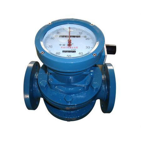
Waistwheel flowmeter
- Tel:0550-7591188
- Fax:0550-7591188
- Email:2136705934@qq.com
Description
1. Product overview:
LL series lumbar flowmeter is a volumetric flow measuring instrument. The measuring part is made of stainless steel and has strong anti-corrosion performance. It can be used for flow measurement of water-containing corrosive crude oil or other corrosive media. The flowmeter can display the cumulative flow on site and is equipped with a remote transmission output interface. It can be equipped with a photoelectric converter to output electrical pulse signals or analog signals. It can be matched with a flow totalizer for remote measurement, display and control.
The structure is characterized in that a metering chamber is arranged in the casing of the flowmeter, and one or two pairs of tangentially rotatable waist wheels are arranged in the metering chamber. A pair of transmission gears are installed coaxially with the two search wheels outside the casing of the flowmeter, and they mesh with each other so that the two waist wheels can be linked with each other.
It can accumulate flow on site, and is equipped with a remote transmission output interface. It can be equipped with a photoelectric converter to output pulse signal or analog signal, and it can be matched with a flow totalizer for remote measurement display and control.
LL series waist wheel flowmeter is mainly composed of three parts: measuring cavity, sealing coupling and counter. The cumulative flow and instantaneous flow can be indicated on the spot, and together with a transmitter and a flow intelligent controller, it can realize long-distance measurement and control. Widely used in petroleum, chemical, electric power, metallurgy, transportation, food processing, medicine, national defense, commercial trade and other departments to accurately measure oil, petroleum products, chemical solutions and other fluids.
2. Working principle:
LL series waist wheel flowmeter is that when the liquid to be measured flows through the measuring chamber, a pressure difference is formed at the inlet and outlet of the flowmeter, and the waist wheel rotates under the impetus of this pressure difference. At the same time, through a pair of driving gears fixed on the shaft of the waist wheel, the two waist wheels keep rotating continuously. With the rotation of the waist wheel, the liquid is continuously discharged from the flow meter through the metering chamber. The amount of liquid flowing through each pair is four times the volume of the metering chamber. Through the sealed coupling and deceleration mechanism, the number of rotations is decelerated and transmitted to the counter, which indicates the instantaneous flow and cumulative flow of the liquid. Installing the transmitter in the counter mechanism becomes a waist wheel with transmitter. Matched with display instrument or computer system, it can realize automatic measurement and control of remote transmission (quantitative, cumulative, instantaneous and other functions). See also display instrument classification manual for usage instructions.
3. Application measurement:
LL type can be used for flow measurement of high viscosity liquids such as pure crude oil and heavy oil;
LL-D sand control type can be used for flow measurement of sandy crude oil, heavy oil and other high viscosity fluids;
The part of the LL-F stainless steel flowmeter in contact with the medium is made of stainless steel, which has strong anti-corrosion performance and can be used for flow measurement of corrosive liquids, especially in the chemical industry;
LY-C light oil type is especially suitable for flow measurement of low viscosity fluids such as light oil and diesel.
Fourth, the main features:
1. High measurement accuracy, the basic error can generally reach plus or minus 0.2% to plus or minus 0.5%, and it can reach plus or minus 0.1% in special requirements. The characteristics of the flowmeter are generally not affected by the flow state, nor the size of the Reynolds number. limits.
2. Can be used for flow measurement of high viscosity liquids
3. The measurement range is wide, the typical flow range is 5:1 to 10:1
4. The word wheel type counter accumulates the total amount of fluid without external energy. The instant noodle counter is used to display the accumulated flow double, one of which can be reset to zero, which is convenient for users to use in the case of discontinuous measurement.
5. There is no contact between the measuring components, no wear, and long service life.
6. The large-diameter flowmeter adopts the rotor form to reduce the noise and vibration of the flowmeter.
Five, technical parameters:
1. Allowable basic error: ±0.1%, ±0.2%, ±0.5%;
2. Nominal diameter DN (mm): 15~300;
3. Nominal pressure PN (M.Pa): cast iron (A), stainless steel (P) 1.0, 1.6, 2.5, 4.0, 6.3; cast steel (E) 2.5, 4.0, 6.3, 9.6;
4. Measured liquid temperature:
a. Low temperature type: -40~+60℃;
b. Normal temperature type -10℃~+80℃;
c. Medium temperature type -10℃~+200℃;
d. High temperature type -10℃~+300℃;
5. Measured liquid viscosity (mPa.s): 0.3~50000;
6. Pipe connection: GB/T9118-2000 (Chinese standard flange); NIST (American standard flange); BSPT (British standard pipe thread): NPT (American push-pull pipe thread);
7. On-site display: 99999,999 L (cumulative flow) 9999,999.9 L (single flow); 9999,999.9 L (instantaneous flow);
8. Output signal: pulse signal, 4~20mA, 1-5V, 4~20mA +HART protocol, MODBUS supports RS232, RS485 communication (optional);
9. Explosion-proof grade: EXiaIIBT5EXiaIICT5 Protection grade: IP65.
6. Installation and use:
1. A filter should be installed in front of the flow meter, and the arrows on the two meter bodies point in the same direction as the flow.
2. When the measured liquid contains gas, a gas separator should be installed in front of the flowmeter.
3. No matter whether the pipeline is installed vertically or horizontally, the waist wheel shaft of the flowmeter is installed in a horizontal position (that is, the dial should be vertical to the ground).
4. When the flowmeter is installed correctly, if the reading is not easy to see, the counter can be rotated 180 degrees or 90 degrees.
5. The throttle valve should be installed at the inlet of the flow meter, and the opening and closing valve should be installed at the outlet. When using the opening and closing valve, it should be started slowly, and the valve should not be opened suddenly.
6. It is strictly forbidden to use the sweeping steam to pass through the flow meter.
7. In the continuous use department, the flowmeter needs to add a bypass pipeline.
8. Before the flowmeter is installed, the pipeline needs to be flushed. When flushing, use a straight pipe section (replacement of the flowmeter position) to prevent welding slag and debris from entering the flowmeter.
9. It is strictly forbidden to use water to calibrate the flowmeter composed of cast iron and cast steel.
10. When the flowmeter is in use, the flow rate shall not exceed the technical requirements. The flowmeter works normally at 70~80% of the maximum flow.
11. If the liquid to be tested is chemically corrosive, a flowmeter made of stainless steel should be used. If it is highly corrosive, a flowmeter made of 0Crl8Ni12MO2Ti should be used.
